- Fundamentals of design
- Design of joints, levers and offset links
- Design of shafts, keys and couplings
- Design of power screws
- Design of springs
- Design of bolted and welded joints
- Selection of anti-friction bearings and gears
Design of joints, levers and offset links
1 Identify the machine element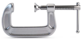
- (A) Offset link
- (B) C clamp
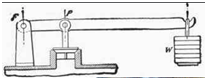
- (C) Hand lever
- (D) Foot lever
2 Identify the machine element
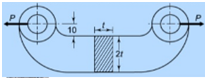
- (A) Offset link
- (B) C clamp
- (C) Hand lever
- (D) Foot lever
3 The maximum stress under bending and axial loading will be
- (A) σb + σa
- (B) σb – σa
- (C) σb + σb
- (D) None
4 Eccentric load causes
- (A) Only bending stress
- (B) Only normal stress
- (C) Bending and normal stress g
- (D) None
5 If M is the bending moment, σb is bending stress and Z is section modulus, then relation between them is
- (A) σb= M.Z
- (B) σb= M/Z
- (C) σb= Z/M
- (D) Z=σb/M
6 If load is acting away from the longitudinal axis of column, it is called _____________.
- (A) Horizontal load
- (B) Axial load
- (C) Eccentric load
- (D) Vertical load
7 The distance between fulcrum and dead weights is 100mm. Dead weights are of 2945.2N. An effort of 294.52N acts on the other hand. Find the distance between the fulcrum and other end of the lever.
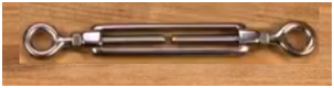
- (A) 1000mm
- (B) 100mm
- (C) 10mm
- (D) 10000mm
8 In levers
- (A) Mechanical advantage is more than leverage
- (B) Mechanical advantage is less than leverage
- (C) Mechanical advantage is equal to leverage
- (D) None of the above
9 The bell crank lever in centrifugal governor is
- (A) First type of lever
- (B) Second type of lever
- (C) Third type of lever
- (D) None of the above
10 The lever loaded safety valve mounted on boiler is
- (A) First type lever
- (B) Second type lever
- (C) Third type lever
- (D) None of the above
11 Identify the lever in the figure
- (A) Bell crank lever
- (B) Hand lever
- (C) Foot lever
- (D) Lever loaded safety valve
12 The cross-section of the arm of a bell crank lever is
- (A) Rectangular
- (B) Elliptical
- (C) I-section
- (D) Any one of the above
13 The cross-section of lever is subjected to
- (A) Torsional moment
- (B) Axial tensile force
- (C) Bending moment
- (D) Axial compressive force
14 The fulcrum pin of lever is designed on the basis of failure due to
- (A) Torsional moment
- (B) Axial tensile force
- (C) Bending moment
- (D) Bearing pressure
15 The bell crank levers used in railway signalling arrangement are of third type levers.
- (A) TRUE
- (B) FALSE
16 The unit of Torque in SI units
- (A) kg-m
- (B) kg-cm
- (C) N-m
- (D) N/ m2
17 A lever is a
- (A) rigid bar
- (B) flexible bar
18 Which of the statement is correct?
- (A) The thickness of the lever is kept uniform throughout
- (B) The width of the levers tapered at the ends
- (C) The bending moment is the lever is maximum near the boss
- (D) All of the above
19 The effort or force applied by a man is normally taken as
- (A) 100 N
- (B) 200 N
- (C) 300 N
- (D) 20 kg
20 Which of the following is not a part of design procedure of a hand lever?
- (A) Shaft design
- (B) Key design
- (C) determination of lever cross section
- (D) Bearing design
21 The section modulus for a rectangular lever is( if b=breadth and t=thickness of lever)
- (A) 1/12 bt2
- (B) 1/6 b t2
- (C) 1/12 tb2
- (D) 1/6 tb2
22 The square key has
- (A) same length and breadth
- (B) length double the breadth
- (C) breadth double the length
- (D) length triple the breadth
23 The force exerted by a man by foot is normally taken as
- (A) 200 N
- (B) 400 N
- (C) 600 N
- (D) 40 kg
24 The design of a foot lever is much the same way as the hand lever; the only difference is that the handle is replaced by a foot plate.
- (A) TRUE
- (B) FALSE
25 The bell crank lever is
- (A) a straight lever
- (B) a two arm lever which are right angle to each other
- (C) a two arm lever with an acute angle
- (D) a three arm lever
26 On a lever, the fulcrum is
- (A) The point the lever balances, or pivots, on
- (B) The object being lifted or moved
- (C) The point where force is applied to the lever
- (D) The spot where the lever is weakest
27 On a lever, the load is
- (A) The point where force is applied to the lever
- (B) The centre of gravity
- (C) The point the lever balances, or pivots, on
- (D) The object being lifted or moved
28 On a lever, the effort is
- (A) The spot where the load is placed
- (B) The point where force is applied to the lever
- (C) The object being lifted or moved
- (D) The point the lever balances, or pivots, on
29 Mechanical advantage is the ratio of effort to load
- (A) TRUE
- (B) FALSE
30 Leverage is the ratio of effort arm to load arm
- (A) TRUE
- (B) FALSE
31 How many classes of levers are there?
- (A) 2
- (B) 3
- (C) 4
- (D) 5
32 Fulcrum can be located at one end of the lever.
- (A) TRUE
- (B) FALSE
33 Class 1 levers have
- (A) Effort between the load and the fulcrum
- (B) Fulcrum placed between the effort and load
- (C) Load in-between the effort and the fulcrum
- (D) None
34 Class 3 levers have
- (A) Effort between the load and the fulcrum
- (B) Fulcrum placed between the effort and load
- (C) Load in-between the effort and the fulcrum
- (D) None
35 Which distance is more important from the fulcrum for a lever
- (A) Distance of load to be lifted
- (B) Distance of the force applied
- (C) Distances of both load as well as of effort
- (D) None
36 Which of the following mechanical joints is used when small amount of flexibility or angular moment of the axis of the rods is necessary?
- (A) Socket and spigot joint
- (B) Gib and cotter joint
- (C) Knuckle joint
- (D) Turnbuckle
37 The function of the split pin/ taper pin of a knuckle joint is
- (A) It holds the collar secure
- (B) It prevents the lifting of the knuckle pin from the joint
- (C) It prevents the dismantling of the joint accidentally
- (D) All the above reasons
38 The empirical relation used for estimating the thickness of the single eye of the knuckle joint is
- (A) t = 1.00 d
- (B) t = 1.25 d
- (C) t = 1.50 d
- (D) t = 1.75 d
39 Turn buckle is used to connect two members which are subjected to
- (A) Tensile loading
- (B) Compressive loading
- (C) Shear loading
- (D) Bending loading
40 Which of the following mechanical joints is used when slight adjustment of length or tension under loaded conditions is necessary?
- (A) Socket and spigot joint
- (B) Gib and cotter joint
- (C) Knuckle joint
- (D) Turnbuckle
41 If a screw thread advances in the nut when turned in a clockwise direction, it is called _________
- (A) left hand helix
- (B) right hand helix
- (C) clockwise helix
- (D) anticlockwise helix
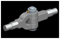
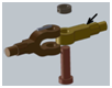
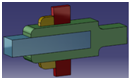
42 Identify the joint given in the figure
- (A) Socket and spigot joint
- (B) Gib and cotter joint
- (C) Sleeve and cotter joint
- (D) Knuckle joint
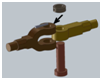
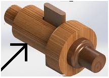
43 Name the part to which the arrow points in the given figure
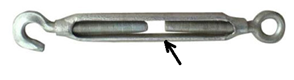
- (A) Nut
- (B) Right handed thread
- (C) Left handed thread
- (D) Coupler
44 Turn buckle has
- (A) Right hand threads on both ends
- (B) Left hand threads on both ends
- (C) Left hand threads on one end and right hand threads on other end
- (D) No threads
45 A turn buckle is used to connect two round rods subjected to tensile loading and requiring subsequent adjustment for tightening or loosening.
- (A) Yes
- (B) No
46 Which of the following joints is used for connecting rods that rotate?
- (A) Socket and spigot joint
- (B) Gib and cotter joint
- (C) Sleeve and cotter joint
- (D) None of the above
47 In case of cotter joint the material used for cotter is
- (A) Cast iron
- (B) Plain carbon steel
48 Diameter of the rod for all mechanical joints is calculated considering the failure in
- (A) Tension
- (B) Shear
- (C) Compression
- (D) None of the above
49 What type of force do mechanical joints transmit
- (A) Axial force
- (B) Torque
- (C) Bending
50 For a plain carbon steel three strengths 100 MPa, 60 MPa and 40 MPa are given. Choose the correct names of the strengths.
- (A) Tensile strength-100 MPa, compressive strength-60 MPa and shear strength-40 MPa
- (B) Tensile strength-60 MPa, compressive strength-100 MPa and shear strength-40 MPa
- (C) Tensile strength-40 MPa, compressive strength-60 MPa and shear strength-100 MPa
- (D) Tensile strength-100 MPa, compressive strength-40 MPa and shear strength-60 MPa
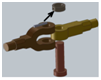
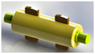
51 Identify the joint given in the figure
- (A) Socket and spigot joint
- (B) Gib and cotter joint
- (C) Sleeve and cotter joint
- (D) Knuckle joint
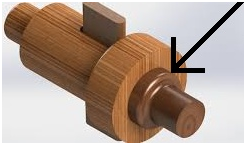
52 Identify the part of the knuckle joint shown by the arrow in the given figure

- (A) Pin
- (B) Collar
- (C) Singe eye
- (D) Taper pin
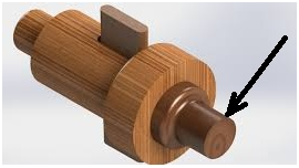
53 Identify the part of the knuckle joint shown by the arrow in the given figure
- (A) Pin
- (B) Collar
- (C) Singe eye
- (D) Taper pin
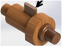
54 Identify the part of the knuckle joint shown by the arrow in the given figure
- (A) Pin
- (B) Collar
- (C) Singe eye
- (D) Taper pin
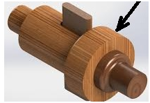
55 Identify the part of the knuckle joint shown by the arrow in the given figure
- (A) Pin
- (B) Collar
- (C) Singe eye
- (D) Fork
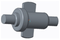
56 Identify the joint given in the figure
- (A) Socket and spigot joint
- (B) Gib and cotter joint
- (C) Sleeve and cotter joint
- (D) Knuckle joint
57 Identify the joint given in the figure
- (A) Socket and spigot joint
- (B) Gib and cotter joint
- (C) Sleeve and cotter joint
- (D) Knuckle joint
58 Identify the joint given in the figure
- (A) Socket and spigot joint
- (B) Gib and cotter joint
- (C) Sleeve and cotter joint
- (D) Knuckle joint
59 Identify the machine element shown in the figure

- (A) Cotter
- (B) Gib
- (C) Sleeve
- (D) Collar
60 Which of the following cotter joint will be used to connect strap end of a connecting rod
- (A) Sleeve and cotter joint
- (B) Spigot and socket cotter joint
- (C) Gib and cotter joint
- (D) Any one of these
61 61 Which type of rod-joint is used for rods of square cross section?
- (A) Sleeve & Cotter Joint
- (B) Socket and Spigot Joint
- (C) Gib and Cotter Joint
- (D) Knuckle Joint
62 Taper usually provided on cotter is
- (A) 1 in 10
- (B) 1 in 24
- (C) 1 in 40
- (D) 1 in 50
63 In a gib and cotter joint, the gib and cotter are subjected to
- (A) Single shear only
- (B) double shear only
- (C) Single shear and crushing
- (D) double shear and crushing
64 The number of cotters used in an assembly of sleeve and cotter joint are
- (A) One
- (B) Two
- (C) Three
- (D) Four
65 Which type of joint you can assemble with the parts shown in the figure?
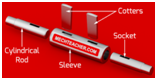
- (A) Socket and spigot joint
- (B) Gib and cotter joint
- (C) Sleeve and cotter joint
- (D) Knuckle joint
66 There are three distinct parts in a socket and spigot cotter joint. They are
- (A) A washer, a nut and a bolt
- (B) A cotter, a nut and a bolt
- (C) A cotter, a socket and a bolt
- (D) A cotter, a socket and a spigot
67 The rod in a socket and spigot cotter joint is designed considering failure in tension, because
- (A) A material is stronger in compression and weaker in tension
- (B) A material is weaker in compression and stronger in tension
- (C) A material is equally strong in both compression and tension
- (D) A material is experiencing only tension and not compression
68 When the spigot collar in a socket and spigot cotter joint fails in shear, the resisting area is given by
- (A) A=(π/4).d12
- (B) A= π.d1.t1
- (C) A=( π /4)/(d1.t1)
- (D) A=d1.t1
69 The spigot end of a socket and spigot cotter joint may fail in shearing when the joint is subjected to a tensile force. This shearing failure is
- (A) Single shear failure
- (B) Double shear failure
- (C) Triple shear failure
- (D) Quadruple shear failure
70 The thickness of the cotter is generally taken equal to
- (A) 0.5d
- (B) 0.4d
- (C) 0.31d
- (D) 0.1d
71 A cotter joint is having a maximum draw of
- (A) 10 mm
- (B) 5 cm
- (C) 8 mm
- (D) 3mm
72 The piston rod of a steam engine is usually connected to the cross head by means of
- (A) bolted joint
- (B) knuckle joint
- (C) cotter joint
- (D) universal joint
73 Figure shows the shearing failure of cotter in a cotter joint. The area of failure is
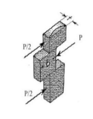
- (A) A= b.t
- (B) A= 2.b.t
- (C) A=(P/2).t
- (D) A=b.t/2
74 The strength equation when a cotter fails is shearing is
- (A) σt = P/(b.t)
- (B) σt = P/(2.b.t)
- (C) τ = P/(b.t)
- (D) τ = P/(2.b.t)
75 The formula for the shaded area is
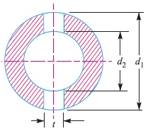
- (A) A= π/4. (d22-d12) – (d1– d2).t
- (B) A= π/4. (d12– d22)
- (C) A= π/4. (d12– d22) – (d1– d2).t
- (D) A= π/4. (d12– d22) – d1.t
76 Name the part of the cotter joint pointed by the arrow
- (A) Rod
- (B) Socket
- (C) Socket collar
- (D) Spigot collar
77 Name the part of the cotter joint pointed by the arrow
- (A) Rod
- (B) Socket
- (C) Spigot collar
- (D) Cotter
78 Name the part of the cotter joint pointed by the arrow
- (A) Rod
- (B) Socket
- (C) Socket collar
- (D) Spigot collar
79 Name the part of the cotter joint pointed by the arrow
- (A) Rod
- (B) Socket
- (C) Socket collar
- (D) Spigot collar
80 Name the part of the cotter joint pointed by the arrow
- (A) Rod
- (B) Socket
- (C) Socket collar
- (D) Spigot collar
81 The draw of cotter should not be more than
- (A) 3 mm
- (B) 6 mm
- (C) 8 mm
- (D) 12 mm
82 A cotter is used to
- (A) rigidly connect rods
- (B) transmit motion
- (C) prevent rotation of rods
- (D) all of the above
83 A cotter joint may fail due to
- (A) shearing
- (B) bending
- (C) crushing
- (D) all of the above
84 Cotter joints is used for withstanding
- (A) Axial compressive load
- (B) Axial tensile load
- (C) Axial tensile or compressive load
- (D) Twisting load
85 Taper on the cotter and slot is provided
- (A) on both the sides
- (B) on one side only
- (C) on none of the sides
- (D) may be provided anywhere
86 Cotter joint is used when the members are subjected to which type of stresses?
- (A) Axial tensile
- (B) Axial compressive
- (C) Axial tensile or compressive
- (D) None of the mentioned
87 A taper is provided for cotter
- (A) To ensure tightness in operation condition
- (B) To provide wedge action
- (C) To ease the removal of cotter during dismantling
- (D) For all three reasons
88 The principle of wedge action is used in cotter joint.
- (A) TRUE
- (B) FALSE
89 Which of the following is not a part of cotter joint?
- (A) Socket
- (B) Spigot
- (C) Cotter
- (D) Collar
90 Cotter joint can be used to connect two rods for torque transmission purpose.
- (A) TRUE
- (B) FALSE
91 A cotter joint is used to connect two __________ rods.
- (A) Co-axial
- (B) Perpendicular
- (C) Parallel
- (D) None of these
92 Cotter joint is connected to parallel roads
- (A) TRUE
- (B) FALSE
93 In case of a cotter joint the compressive load is transmitted from one rod to another rod
- (A) Directly
- (B) Via cotter
- (C) Via cotter pin
- (D) Via collar
94 Taper is made on both the sides in cotter and in the slot
- (A) Yes
- (B) No
95 Taper on Cotter is varies from
- (A) 1 in 15 to 1 in 12
- (B) 1 in 20 to 1 in 15
- (C) 1 in 25 to 1 in 20
- (D) 1 in 48 to 1 in 24
96 The joint in valve mechanism of reciprocation engine is
- (A) Knuckle joint
- (B) Universal joint
- (C) Cotter joint
- (D) Key joint
97 Can the cotter joint be used to connect slide spindle and fork of valve mechanism?
- (A) TRUE
- (B) FALSE
98 Determine the width of the cotter used in cotter joint connecting two rods subjected to axial load of 50kN and permissible shear stress in cotter is 50N/ (mm²). Given thickness of cotter=10mm
- (A) 50mm
- (B) 100mm
- (C) 150mm
- (D) 25mm
99 If joint is to fail by crushing of socket collar then estimate the diameter of socket collar. Given Permissible compressive stress= 126.67 N/mm².; Spigot dia=65mm; thickness of collar=15mm
- (A) 131mm
- (B) 139mm
- (C) 141mm
- (D) 149mm
100 The valve rod in a steam engine is connected to an eccentric rod by
- (A) cotter joint
- (B) bolted joint
- (C) knuckle joint
- (D) universal coupling